20 KiB
Final Project - Network Tap/MitM
For this project, I will be constructing my transparent network tap / monster-in-the-middle device using a raspberry pi 3B+ (hostname pitap)
Background
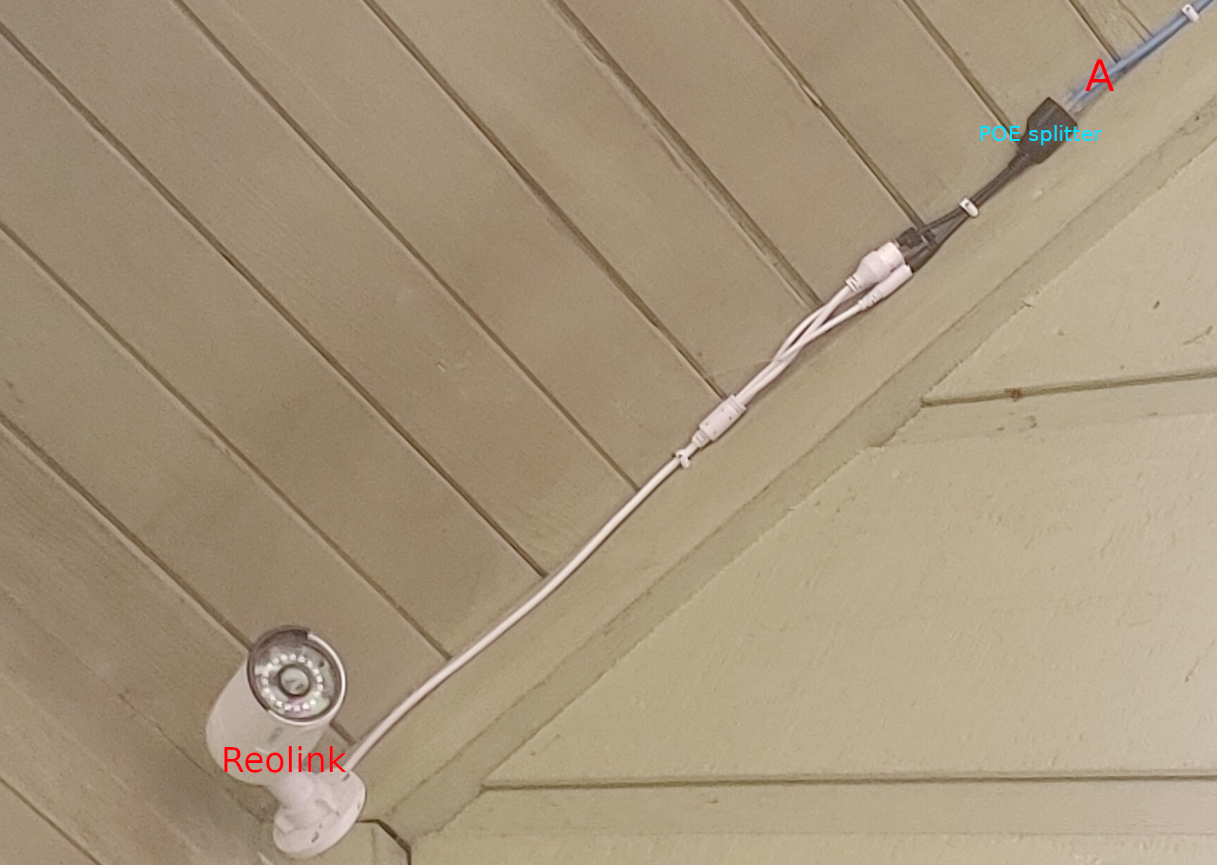
This device will be constructed and deployed on my home network. Specifically, I will insert this device between an IP camera I own (hostname reolink) and a network switch, which connects to the rest of my home homework, including my desktop from which I normally access the cameras RTSP stream or HTTP web interface.
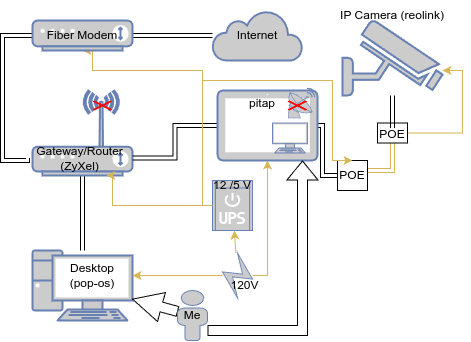
At this point, I have physically configured my network to support this project, so let's take a look. Here is a rough sketch.
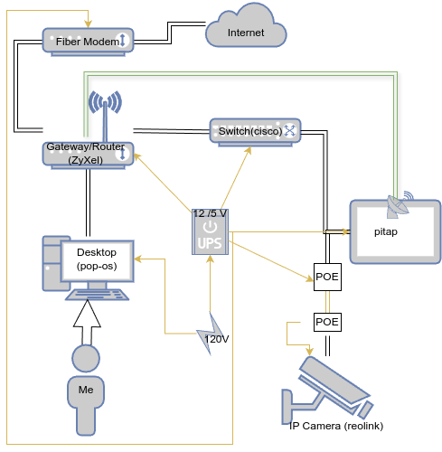
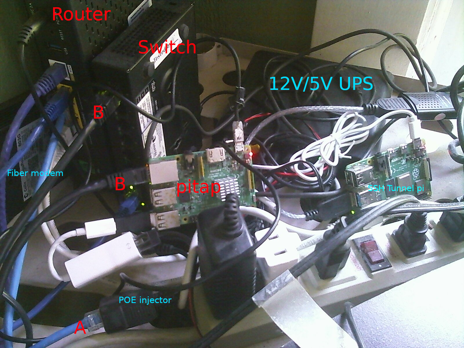
And here are a couple photographs of the hardware - the parts most relevant networking-wise are in red.
For reference, here is a table of the relevant devices
| Device | Adapter | MAC | IP |
|---|---|---|---|
| Router (ZyXel) | WAN | 08:26:97:5B:9A:01 | 97.120.207.11 |
| Router (ZyXel) | LAN (eth+wl) | 08:26:97:5B:99:FE | 192.168.0.1 |
| Switch (cisco) | eth | 00:9E:1E:0E:CF:02 | X |
| pitap | eth0 | b8:27:eb:8a:05:87 | 192.168.0.38 (temp) |
| pitap | eth1 | 24:f5:a2:8b:4a:06 | X |
| pitap | wlan0 | b8:27:eb:df:50:d2 | 192.168.0.42 |
| Desktop (pop-os) | enp7s0 | 04:42:1a:93:54:da | 192.168.0.56 |
| IP Camera (reolink) | eth | ec:71:db:d1:1c:ca | 192.168.0.4 (assigned) |
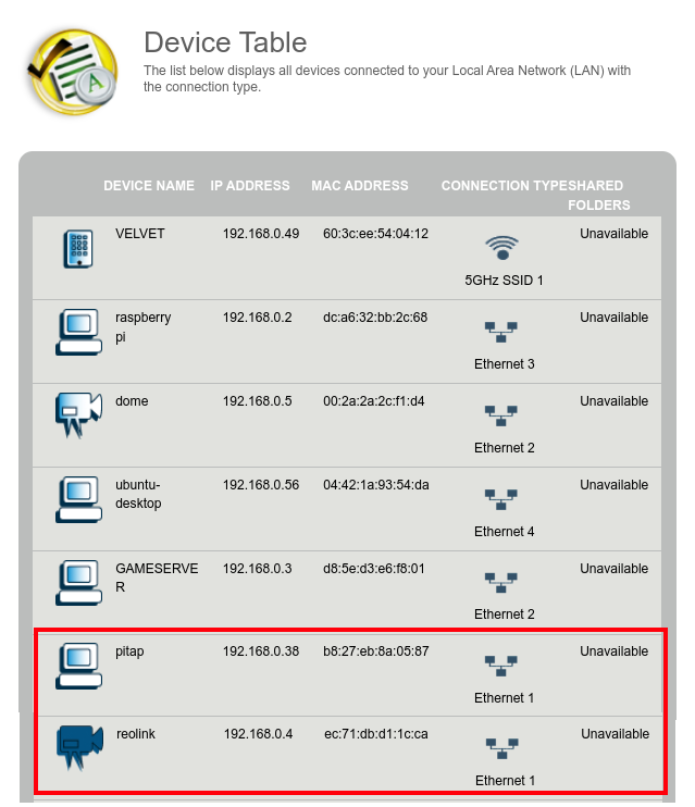
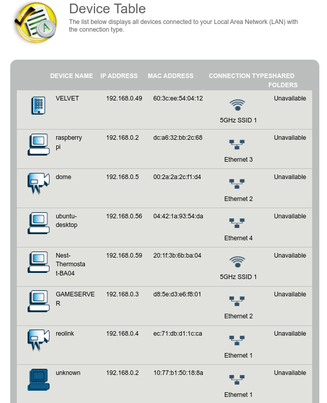
Before proceeding, we should consider how the reolink device will appear on my network upon successfull configuration of the network tap. In my case, the reolink camera has an IP assignment (DHCP reservation) from my gateway of 192.168.0.4

At this time with the current wiring, the reolink appears unavailable to my network, and the pitap is present on the network on ethernet. For the end result, we expect the pi to no longer appear on ethernet (it will then be on wireless), and we expect the reolink device to return to the network on ethernet with the expected hostname, MAC, and IP address that the gateway is already familiar with.
I have other interesting devices connected to my home network, including additional switches, raspberry pi's, IP cameras, wireless extenders, and an active multiplayer game server. These will be ignored.
Baseline statistics
Before moving on to configuration, we should have an idea of the network performance without the pitap so we have something to compare to later on. We hope the pitap will introduce minimal network performance degredation, as this would increase the chance of detection. For this section, I will revert my network by shutting down pitap and plugging the reolink camera back into my switch.
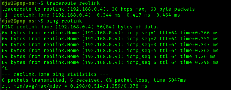
A quick ping shows an average latency of .378ms, and a high spike of 1.36ms
Getting a maximum measurement of theoretical bandwidth is not straightforward. Reolink does not (easily) provide ssh access to the underlying operating system, so I cannot use a tool like iperf3 to test the bandwidth. However, in my current network configuration, I can consider some things to get an idea
- All ethernet cables used support gigabit links (Cat 6 or Cat 5e)
- All of my primary networking devices support gigabit links (desktop PC, switch, router, fiber modem, ISP subscription)
- My reolink camera supports 100 Mbps max ethernet connection
- The PoE being injected to the reolink camera would redundantly limit bandwidth to 100BASE-T given that it uses half of the conductors
- The pi 3b+ is said to have a built-in gigabit network adapter but is limited to ~300Mbp/s since ethernet passes through the USB 2.0 bus
- The belkin USB to ethernet adapter I am using with the pi is rated for gigabit speeds. However, this is also going through the USB 2.0 bus (at the same time), so I expect the overall maximum performance of pitap to be 300Mbps/2 or ~150Mbps
With all this in mind, the bottleneck at the link layer is my reolink camera itself, and I do not expect this performance to be degraded by using the pitap.
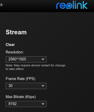
However, we can do a little better to understand the bandwidth I expect to get under normal circumstances. According to my cameras web UI panel, the maximum bitrate it can transmit is 8192 Kbps. This is using its highest performance "Clear" stream with the maximum resolution of 2560x1920, 30 frames per second, and H.264 encoding. As a note, audio is also supported on this stream.
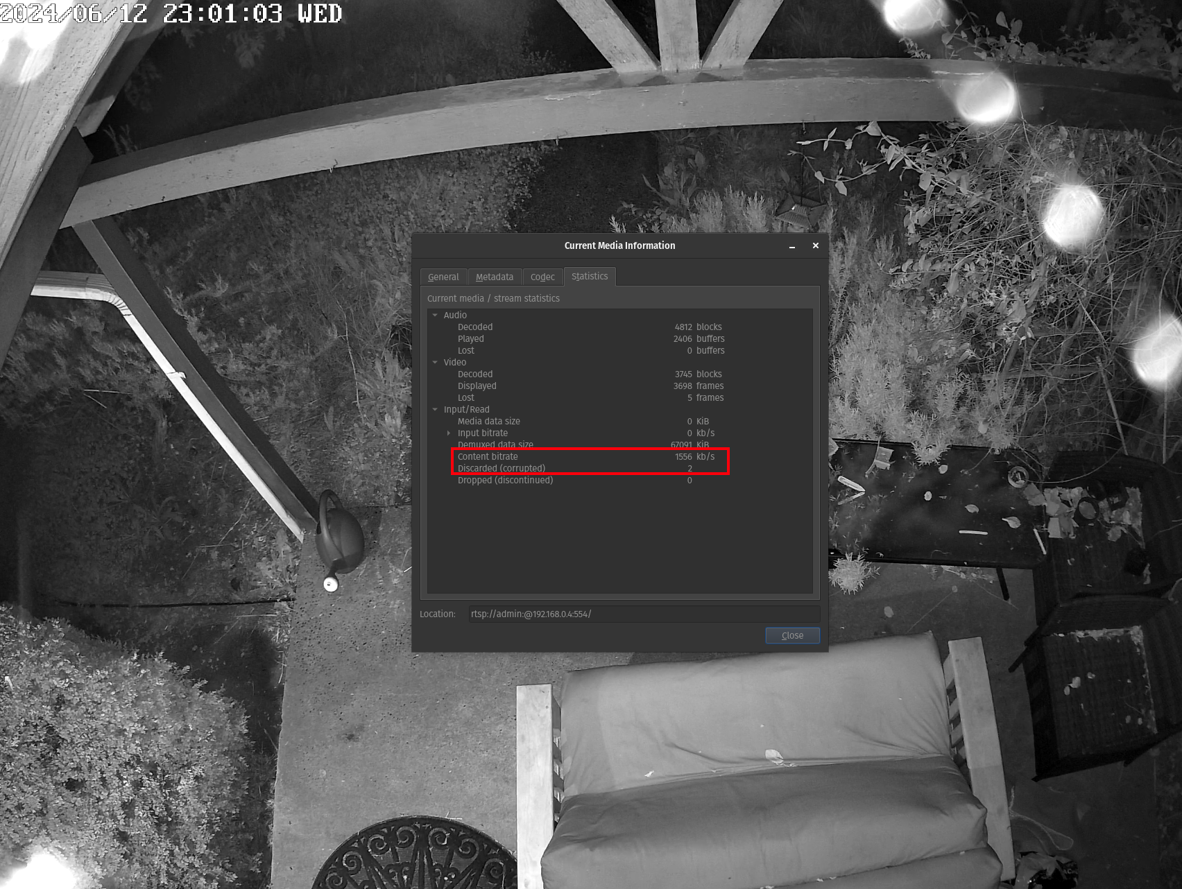
Last, I decided to open the "Clear" RTSP stream in VLC and look at the network statistics
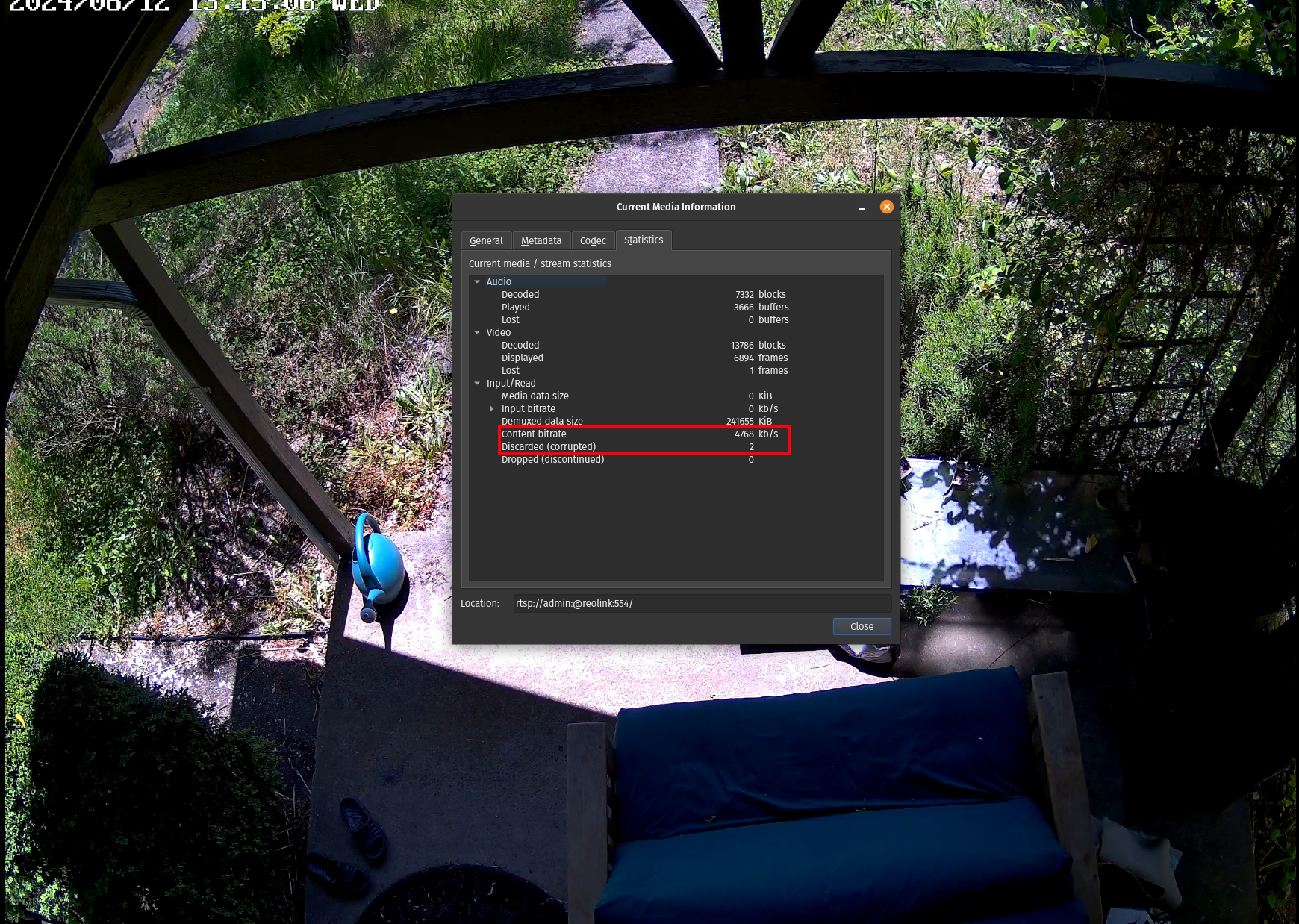
When looking at the content bitrate, the number stays in the range of ~4,500 kb/s to ~12,000 kb/s (low end shown above) consistently flipping between higher and lower values once per second. This aligns very well with the 8192 Kbps maximum bitrate reported by the camera itself. After watching the stream for several minutes, I also notice there are only 2 discarded/corrupted frames. Subjectivly, I can also say the stream is very clear and smooth when viewed fullscreen on my 1440p monitor, with no visual artifacts or stutters.
All said, for the pitap to be "undetectable" the above performance should be maintained.
Pitap Configuration
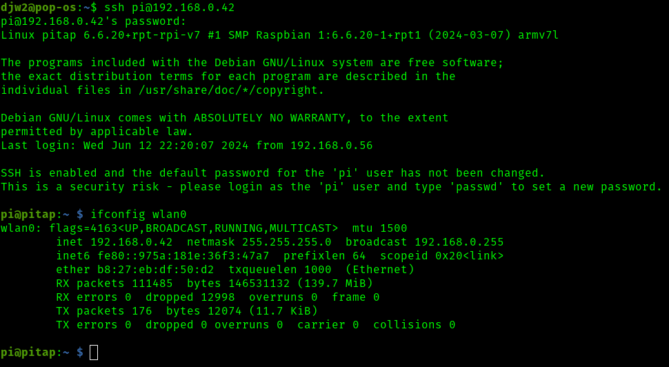
Now the pitap is back on the network and phyiscally connected between the switch and the reolink camera as described in the background. I'll start by ssh'ing to the pi over the wireless IP address (192.168.0.42)
My research shows that bridge-utils is likely to be a good choice to help create the tap. As I understand, this utility is purpose built for creating such bridges at the link layer, but some extra steps will have to be taken to function the same way, yet remain invisible at the link layer. An approach with iptables and forwarding rules may also be possible but I would expect this to be more difficult since iptables seems to operate at the network layer. I have also found a guide which I credit for helping with some of the knowledge needed for this part of the project.
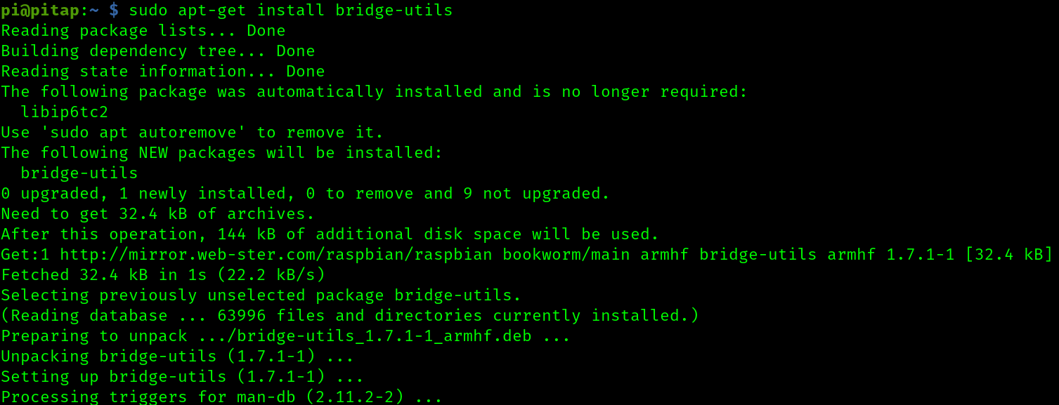
1. Install bridge-utils
This step is straightforward
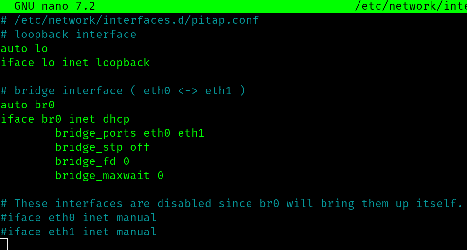
2. New entry /etc/network/interfaces.d/pitap.conf to add the new bridge interface
I start by adding a new network interface configuration here, which is derivative of the one provided by the above mention guide. Modifications were made because I am not interested in changes to the wireless interface, and also I am including this config file as a seperate entry in interfaces.d
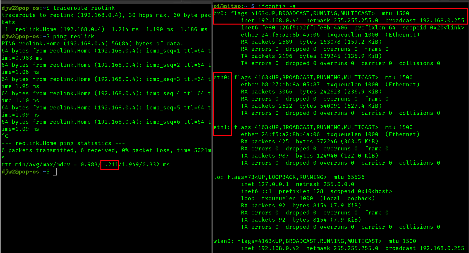
After rebooting the pi, we have some interesting observations. In the terminal on the left, we see that we can now reach the reolink from my desktop. We perhaps have paid a ~1 ms latency for this, but the bridge does work.
However, on the right we see the bridge has an IP address, so it has a presense at the network layer, and this is a problem
3. Improvements for network transparency
First I update /etc/network/interfaces.d/pitap.conf again, and set the br0 interface from dhcp (as seen in the guide) to manual mode. This should help prevent the bridge from trying to ask for an IP address from the gateway
Then, I update /etc/dhcp/dhclient.conf
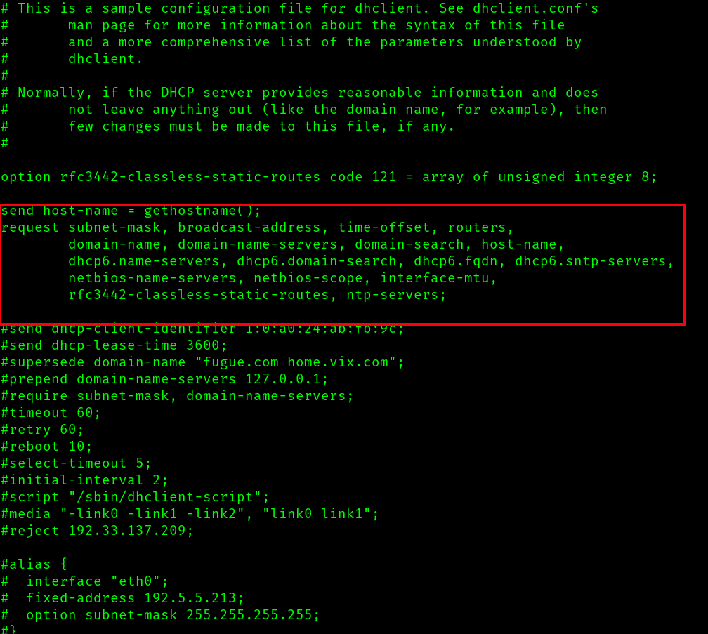
Specifically, I will comment out those active lines and for good measure I add denyinterfaces eth0 eth1 br0. This may be redundant or conflict with the changes to pitap.conf but the goal is that no interface on the tap shall perform any type of dhcp activity.
Now I will reboot the pi and attempt to validate results
4. Validation
To help with validating the transparency of pitap, I have made a few simplifications
- Removed the cisco network switch, and plugged the pitap directly into my router
- Disabled wifi on the pitap to avoid confusion about it's visiblity on my network (
sudo ip link set wlan0 down) - Connected periphrals to the pitap so I can interface with it
- Put the pitap on a dedicated power supply to avoid brownouts
Pitap adapter info
The following iwconfig -a shows us the pitap does not have any assigned IP addresses on our network. Aside from a link local Ipv6 assigned to br0. I do not fully understand the implication of this, but I do not think it matters. Overall, this is a good sign

Router admin panel
The router admin panel shows us the reolink appears with the expect IP and MAC (192.168.0.4 and ec:71:db:d1:1c:ca), just as it did before using the tap. Another good sign
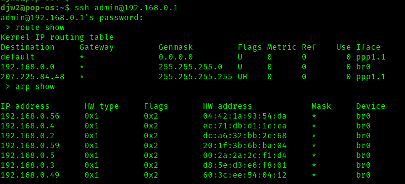
Router and ARP table
The route table (on my router) shows that all LAN traffic is itself going through a bridge (br0) on the router, which I then assume uses some sort of MAC address table to determine which physical port to communicate on.
The arp table shows us the IP devices and their associated MAC addresses, and we confirm that none of the MAC addresses associated with the pitap appear here.
Though things look good, at this point I face a final roadblock in confirming my network tap is transparent. I would like to view the MAC address table/Content Addressable Memory which as I understand would show associations between MAC addresses and physical ports on my router, entirely at the link layer. This table could prove or disprove that the link layer in my router has not 'learned' any MAC address of the pitap and that true transparency is achieved. If it was not, I would go back and re-visit my configuration step.
The issue is that my lousy ISP provided router does not seem to make viewing this possible, either in the web UI or terminal. The terminal claims to provide the command brctl but it is broken and returns no output. The terminal also provides an elevated sh command which could possibly help but that is locked down by an unknown password. Likewise, reolink does not provide any kind of shell access for me to check its MAC address table.
The next step would be for me to flash a new firmware like OpenWRT on my router to get this information. I can not do that at this time as I run a game server with active players on my network and any issues with the firmware upgrade risk causing an extended outage or brick my router. When I aquire another router in the future, this upgrade will then be possible.
In conclusion, I know pitap is transparent at the network layer, and it may also transparent at the link layer but I can not confirm or deny that.
Connecting to reolink
I am able to access the stream again on the reolink with no issues, and video quality appears good. However, we can see that the content bitrate is now lower than before, appering in the range of 1,400 kb/s to 5,500 kb/s with an average of about 3,450 kb/s. This could be because of a bandwidth bottleneck in the pitap, or because now it is dark outside and H.264 can work more efficiently with less color in the image. In this regard I am not sure.
Like before, discarded/dropped frames number only 1 or 2 over a period of several minutes. This is good.
5. Capture + Forward
Now it is time to do something interesting with pitap by capturing and forwarding the traffic.
The script capture.py is intended to do just this. Using scapy, the script works by sniffing all traffic on an interface provided from arguments, and saving those to a unique timestamped file. Every time a file is saved, it attempts to transmit them to a supplied ip address and port (defaults to my workstation on LAN) with the intention that a listening netcat server can capture and save the contents.
The professional thing to do here would be to connect the raspberry pi via wifi to an entirely seperate network, or even to set it up as an access point so that way it can communicate with a netcat server running off the network I am snooping on. However, since we are no longer evaluating the transparency of the pitap I will keep things simple for the sake of time by just connecting pitap via wifi to my router again. I will also be running the netcat server on my workstation, which is the same one consuming the RTSP stream from reolink while I capture. This should all be fine, since transmission to the netcat server will be exclusively over wifi and not on ethernet.
Here's what the capture process looks like using the script
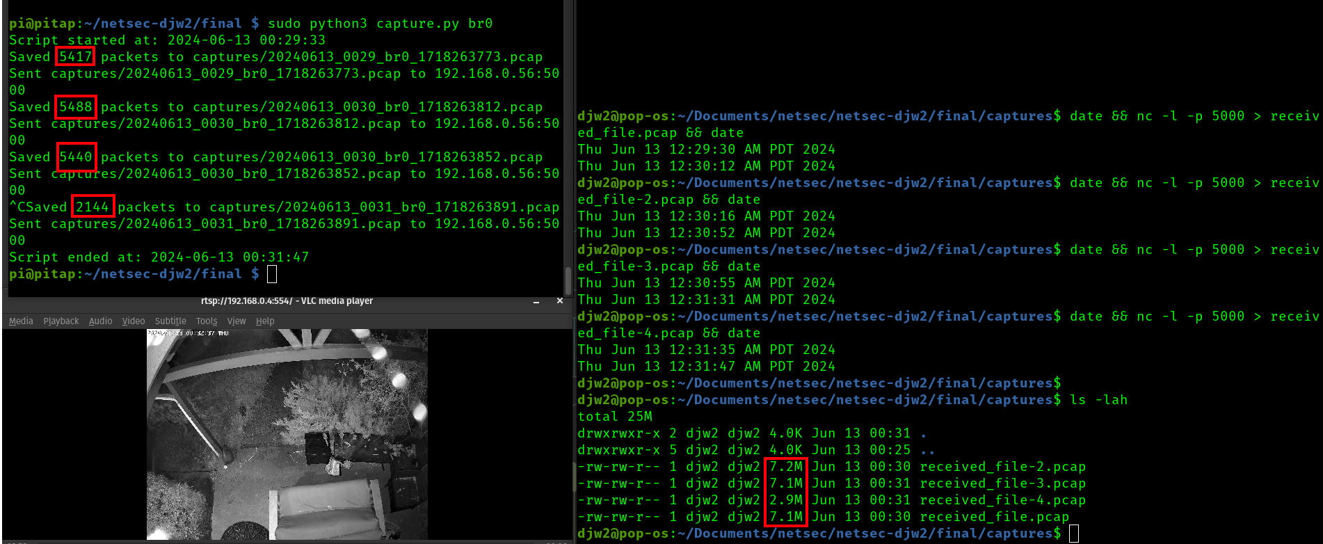
In the top left terminal, pitap is running capture.py with br0. In its current state, this does a scapy sniff for 30 seconds, after which the pcap file is saved and transmitted over a socket connection. In this case, I did not provide an ip or port for that socket, so it defaults to 192.168.0.56:5000 which is my workstation. Also, I manually cut the last capture short to test a graceful stop.
The right terminal is on my local workstation, and I sequentially run date && nc -l -p 5000 > received_file-{num}.pcap && date. This causes netcat to listen on port 5000 and save the incoming contents to a file once the socket closes. I run this a few times to coincide with the 30 second capture windows of the script.
On the bottom left is VLC playing the reolink RTSP stream on my workstation to generate some traffic through pitap.
In a real deployment, I would make improvements to the capture script such as adding the ability to fine tune the capture time, cleaning up old captures that have already been transmitted, running the script as a cron or daemon, etc. Likewise, the netcat server could be made smarter by saving better file names, or be converted to a bash or python script to run automatically/perpetually. However, there is more work to do so let's move on.
The end result is that we have 4 capture files now transmitted off the pitap. These are a consitent 7M in size, with the last one being smaller since the last capture was not 30 seconds.
Analysis
Here is a look at received_file-1.pcap in wireshark. For this capture, I started the stream shortly after capturing, and closed the stream near the end.
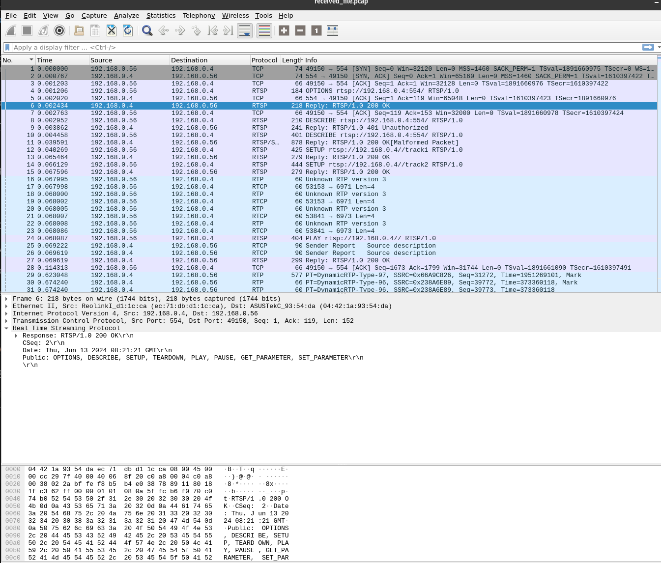
Top of stream - things look good here, setting up the RTSP connection
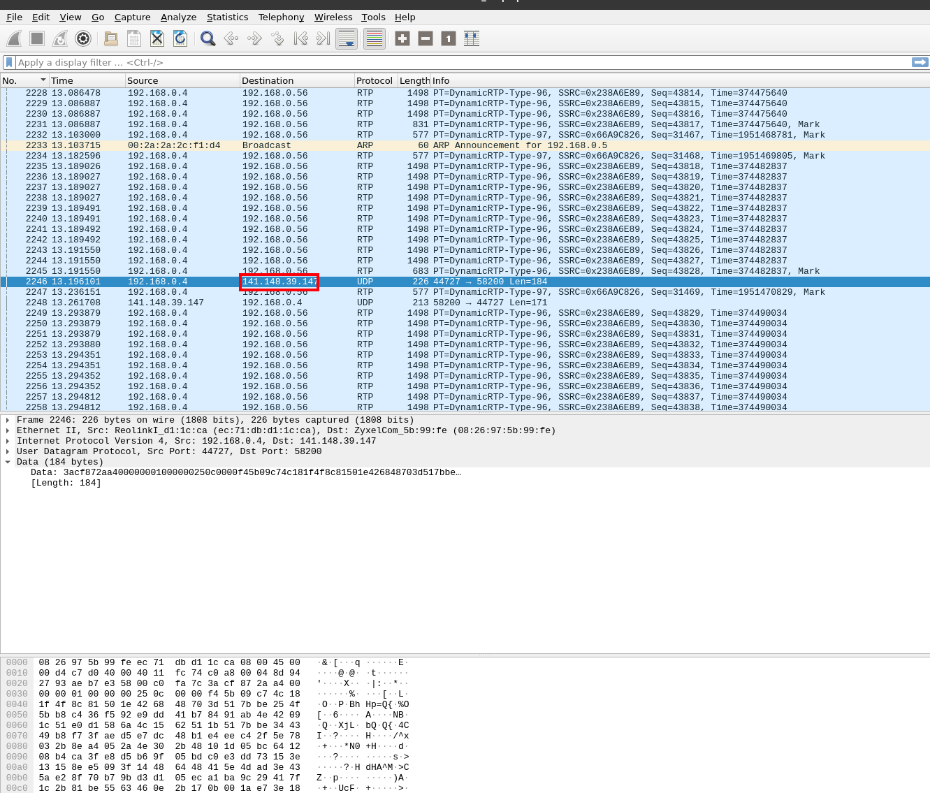
Middle of stream - Most of the capture looks like this, a stream of RTP packets from the camera to my workstation. This is expected, aside from the transmissions to an external IP geo-located in northern Virginia...
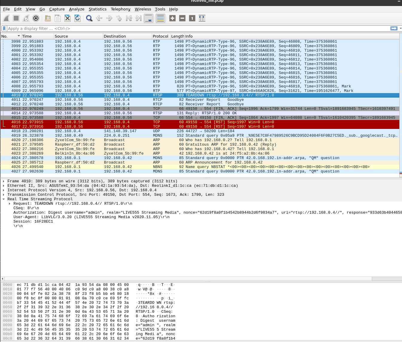
End of stream - This looks ok too, we see the teardown of the RTSP stream. It also seems that APR packets from the pitap wireless interface are making their way back to br0 through the gateway, which makes sense in our configuration
6. Attack
To wrap up, I will create three MiTM style attacks that can be executed by the pitap
6a. TTL=65
This is a simple script found in ttl.py. The idea here is to modify all TTL (time-to-live) values in ipv4 and ipv6 packets passing through the pitap and set them to 65, if they are not already 65. This logic could be extended to include any known packet type which contains a TTL field. We also keep a tally of the number of packets modified
Ultimetly, this script does the job. Here It runs for 2.5 seconds (in the span of this capture that is from 11.12 to 13.42). In this time, it sees 28 ip or ipv6 packets, only one of which already has a TTL of 65. For the rest, the TTL is modified to 65.
The result is that for a brief period of the wireshark capture while I have the RTSP stream running, 28 packets come up in a filter in traffic to the reolink device with a ttl of 65.
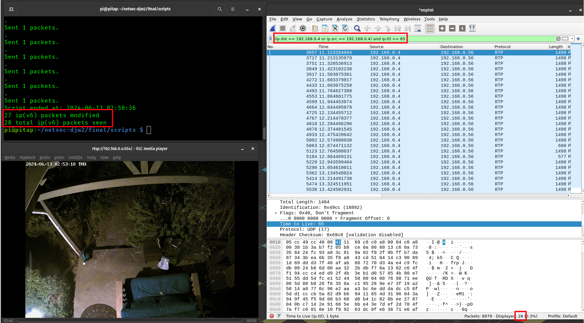
final_1.pcap demonstrates the result of this attack. In an attack like this, setting a high TTL with an invalid destination could overload network resources
6b. HTTP - OK -> NO
At this point I realize my approach with a simple scapy script is flawed. Sniffing and sending packets with scapy does not actually intercept and modify the packets, and instead it just effectively sends a modified copy of the packet out after the operating system has already sent the original. This was noticed when working with TCP packets because of re-transmission error responses.
To proceed, I will install nftables from apt, and netfilterqueue from pip. nftables seems to provide stong capabilities at both layer 2 and 3 traffic, and may help with filtering and queueuing to user space. I first considered just using ebtables but queueing traffic to user space with that was not non-trivial
I want to modify HTTP responses, so I will use the following nftables rules (created with the nft utility) to place the packets we want to modify into a user space queue (NFQUEUE). Then, a python script can access, modify, and explicitly send them
sudo nft add table bridge filter
sudo nft add rule bridge filter forward ip protocol tcp tcp sport 80 queue num 0
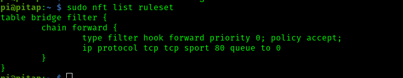
Then, I wrote the script found in http.py. This script combines netfilterqueue to get/send the packets from the nftable queue, and scapy to modify them. This was difficult to get working due to python version issues (some pi bookworm specific), pip issues with the no-longer-maintained netfilterqueue as well as just figuring out the script (like knowing to delete the checksums in the ip and tcp layer). For that reason, this 'attack' is pretty simple and all we do is change 'OK' to 'NO' in http resposes from the reolink web server with status code 200.
However, it did work
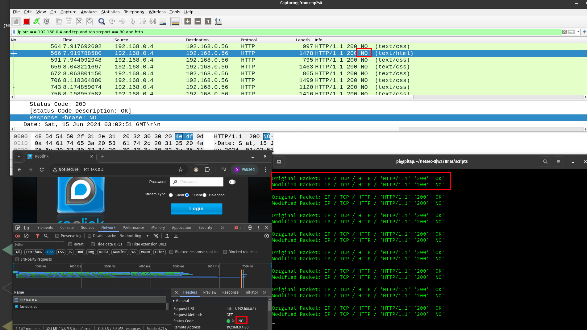
See final_2.pcap. In theory, a similar attack of this nature could be used to return a redict http code and inject additionally inject a Location header to send the user to a malicious web page.
6c. CSS modifications
The final attack will be slightly deeper in the stack. I have written the script css.py which works to find http packets containing css text content and modify their color values to be random. An attack like this, which modifies the user experience could further be applied to malicious concepts like unpermitted advertising, ransom-seeking exploits, or user shock. This concept was tricky to implement because in the tcp stream, the packet which contains the http content-type designating text/css generally itself contains none of the css, and those actually follow in the next couple packets in the stream. So the process involved looking for these http responses with the content type, and identifying the stream primarily by the destination port on my host machine. Once a stream was identified, the next packet was likely to contain the css data, so we try the attack with high confidence. Luckily on our tap, packets tend to travel in order. If on the same stream we see an http packet with a different content type, then we discard that stream and look out for the next one.
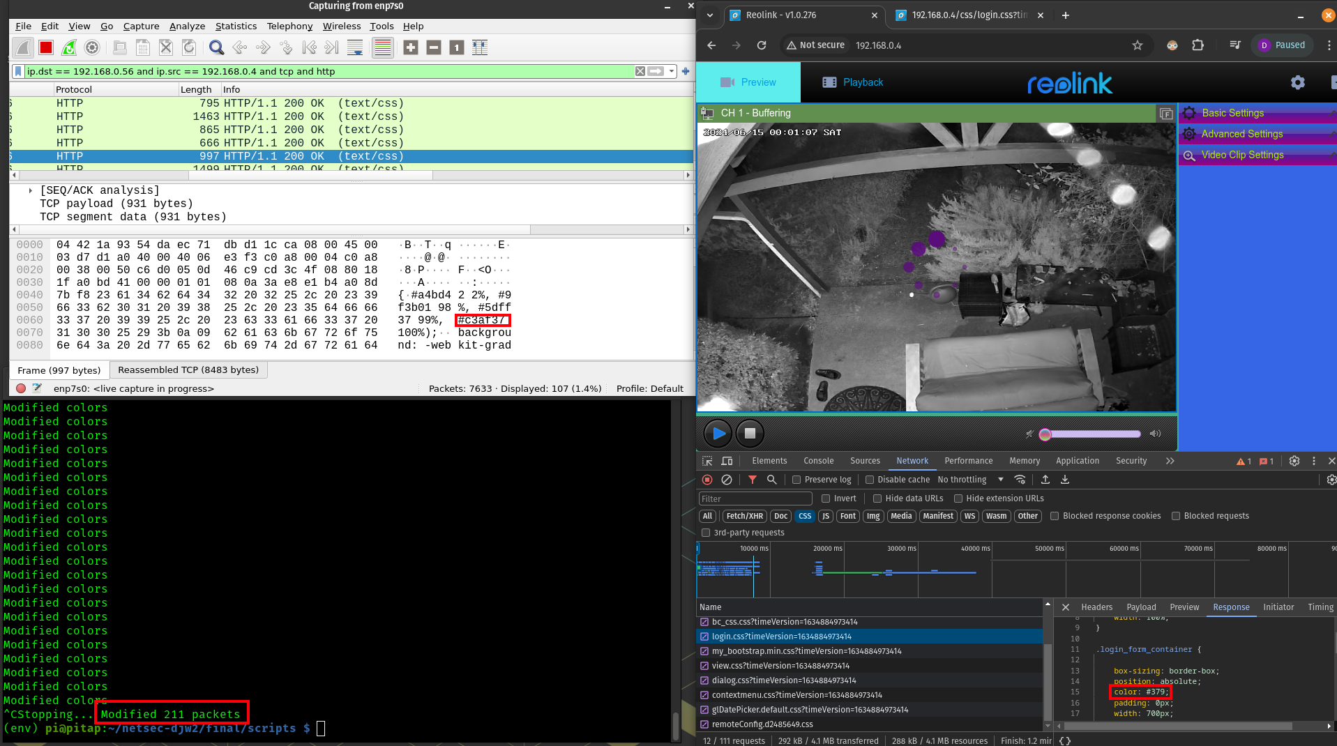 The css attack in action
A more sophisticated version of a similar attack might involve buffering a sequence of TCP packets containing a PNG image, carefully modifying those packets to contain a new PNG image loaded from a local resource, and sending the buffer out all at once. This would be a challenge to do on a live tcp stream.
Another interesting attack would be to modify RTP packets of my RTSP stream (like shown in section 5) to show a new video feed, still image, play a new sound, or show a modified version of the video feed. This would be an ambitious challenge, and anyways I have not yet taken the Introduction to Multimedia Computing course.